What Is a Press Brake and Its Role in Metal Fabrication?
Definition and primary function of press brakes in metalworking
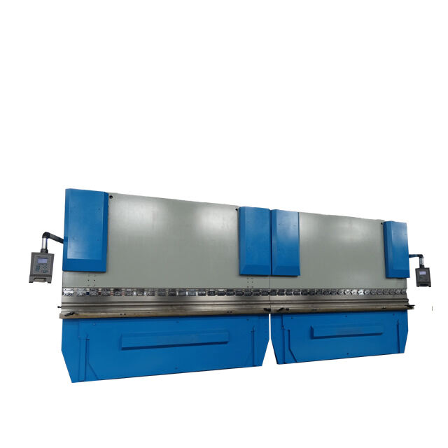
The press brake stands as one of those critical machines used for bending sheet metal accurately through controlled application of force. Basically what happens is the metal gets clamped between two main parts - the punch on top and the die below it. When pressure is applied, we end up with all sorts of bends including standard V shapes, U shapes, or whatever angle the job requires. What makes this whole operation so valuable is how it turns plain flat sheets into actual useful structures such as industrial enclosures, mounting brackets, and various chassis components needed across manufacturing sectors. These days most modern press brakes can hit pretty tight tolerances around plus or minus 0.1 degrees according to Moore Machine Tools from their 2025 data. That kind of accuracy explains why they're found everywhere from car factories to airplane assembly lines and even construction sites where precision matters.
Historical evolution and industrial significance of press brakes
The story of press brakes starts back in those old blacksmith shops of the 19th century. These machines went through quite a transformation over time, moving away from those basic lever systems to more advanced hydraulic versions by the 1950s. During World War II, things really took off as factories needed all sorts of precision parts for planes and other military equipment. Fast forward to today, and according to FMA data from 2023, press brakes handle around 63% of all bending work in American fabrication shops. That number says a lot about how central these machines have become in both large scale production and lean manufacturing practices. What's interesting is that since the 1980s, when computer numerical control got integrated into these systems, manufacturers could suddenly produce really complicated shapes again and again with almost no hands-on work required.
Key Components of a Press Brake: Anatomy of a Bending Machine
Frame, Bed, Ram, Punch, and Die: Core Structural and Functional Parts
Press brakes typically depend on about five main parts to achieve accurate bends in metal. First off, there's this sturdy steel frame that gets welded together. It keeps everything stable when pressure is applied during operation. Then we have the bed attached at the bottom of the frame which holds the lower die in place. On the other side sits the ram component that travels up and down. Depending on what kind of system powers it - hydraulic cylinders, old school mechanical setups, or newer electric servos - the ram pushes the punch against whatever material needs shaping. As this happens, the metal gets forced into the shape of the die below, resulting in those precise bends manufacturers are looking for.
The Punch and Die System: How Tooling Determines Bend Geometry
The angle and radius of bends really comes down to how well the punch matches the die. Standard bends typically come from using a V-shaped punch with its corresponding die setup. When working with acute angle tools though, manufacturers can achieve those tighter radii that are often needed for specific parts. Something important to remember is that the width of the die opening has a big impact on the amount of force required during bending operations. Narrower openings actually need around 30% more force for materials of equal thickness compared to wider dies. This matters a lot when looking at production costs. Companies that maintain good tooling libraries see significant improvements in their workflow because they spend less time changing out tools between different jobs, which makes all the difference in facilities dealing with mixed product runs day after day.
Backgauge and CNC Systems: Enabling Precise Material Positioning
Computer Numerical Control (CNC) systems automate the backgauge, a programmable stop that positions sheets with 0.001" accuracy across multiple axes. Advanced models use laser sensors to detect material irregularities, ensuring consistent bend locations. This automation reduces setup time by 40–60% compared to manual adjustments on non-CNC machines.
Hydraulic, Mechanical, and Servo-Electric Drive Systems Compared
Drive systems define performance characteristics:
- Hydraulic: Dominates heavy-gauge bending (20+ mm steel) with outputs over 6,000 tons, though energy consumption is 15–20% higher than electric alternatives.
- Mechanical: Offers rapid cycling (50+ bends/minute) for lightweight materials but lacks precision and flexibility for modern applications.
- Servo-Electric: Delivers ±0.0002" repeatability and reduces power consumption by 50–70% through energy recovery, ideal for high-precision, low-force tasks.
Hybrid systems now combine hydraulic power with electric control, balancing force and accuracy for smart manufacturing needs.
How Press Brakes Work: The Step-by-Step Bending Process
Operating Principle: From Force Application to Metal Deformation
Metal shaping happens when press brakes apply focused force through a punch into a die, which causes what's called plastic deformation. As the ram moves down, it creates pressure that depends on how thick the material is and its tensile strength. Take stainless steel versus aluminum for instance: stainless needs about 25 to 30 percent more force to bend at the same thickness level. What actually occurs during this process is that the outside parts get stretched while the inside gets compressed together, resulting in those lasting bends we see without any cracks forming in the metal itself.
Step-by-Step Workflow: Alignment, Clamping, Bending, and Retraction
- Alignment: Sheets are positioned against CNC-controlled backgauges with ±0.1 mm accuracy
- Clamping: Hydraulic hold-downs secure the material to prevent slippage
- Bending: The ram drives the punch into the die cavity at 5–15 mm/sec, depending on ductility
- Retraction: Programmable crowning compensates for deflection before full retraction
Material Behavior During Bending: Springback, Stress, and Accuracy
All metals exhibit springback–the partial return to their original shape after force removal. Cold-rolled steel typically springs back 2°–5°, requiring overbending strategies. Thinner materials (<3 mm) show 30% greater springback variation than thicker plates, necessitating real-time angle measurement to maintain ±0.5° tolerances.
Role of CNC in Automating and Standardizing Bending Sequences
Modern CNC systems automate key functions:
- Force adjustment for mixed-thickness batches
- Adaptive correction using springback sensors
- Toolpath optimization to minimize cycle times
- Die library management, reducing setup changes by 40%
Machine learning algorithms now predict bend sequences with 98% accuracy, significantly reducing trial-and-error in custom jobs.
Common Bending Methods: Air Bending, Bottoming, and Coining
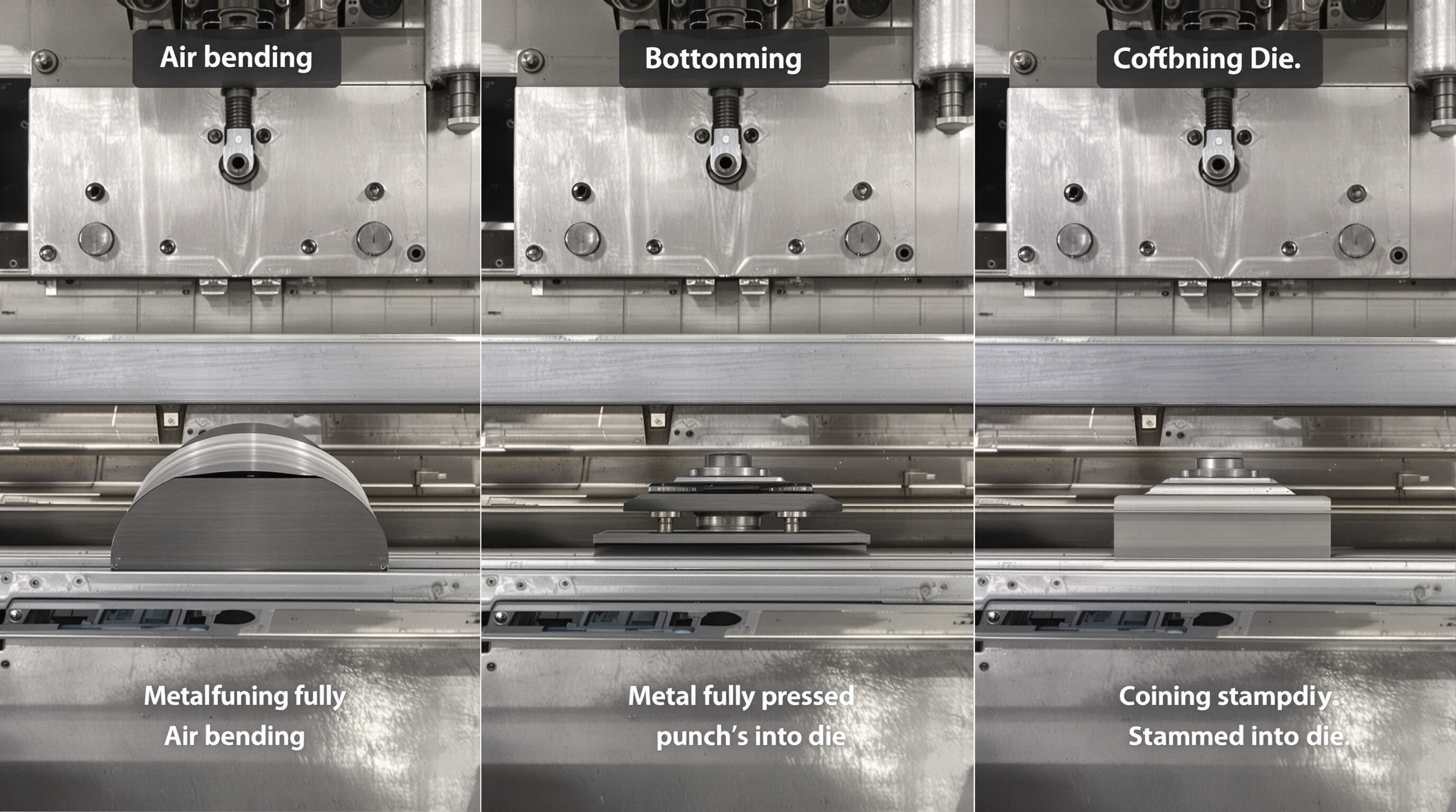
Air bending vs. bottoming vs. coining: Techniques, force requirements, and precision
There are basically three ways press brakes work in metal forming operations. First up we have air bending where there's actually space between the punch and die when shaping metal parts. This method needs about 20 to 30 percent less force compared to other techniques, which makes it pretty efficient for many applications. The downside? Parts tend to spring back around 2 to 5 degrees after forming, so adjustments need to be made for final angles. Then there's bottoming, where the material gets pressed all the way into the die cavity. This takes roughly four to six times more force than air bending, but gives much better precision with plus or minus half a degree accuracy because the metal gets completely deformed plastically during the process. Lastly we come to coining, which really puts the pressure on with eight to ten times the force needed for air bending. This eliminates almost all springback issues, resulting in extremely consistent angles within plus or minus 0.1 degree. That level of precision makes coining perfect for critical components used in aerospace and medical industries. However manufacturers should know that tool wear goes up dramatically here, increasing by about three hundred percent compared to other methods.
Pros and cons of each bending method in production environments
| Method | Advantages | Limitations |
|---|---|---|
| Air Bending | Low tooling costs, multi-angle flexibility | Springback compensation required |
| Bottoming | High repeatability, efficient for batch runs | Requires dedicated dies per angle |
| Coining | Extreme precision for critical applications | 5x energy use vs. air bending |
Force calculations and material thickness impact on method selection
Force requirements scale with material thickness and method:
- Air bending: $ Force = \frac{1.42 \times UTS \times Length \times Thickness^2}{Die\ Opening} $
- Bottoming: 4–6x air bending force
- Coining: 8–10x air bending force
Steel over 5 mm typically requires coining, while thin-gauge aluminum (1–3 mm) is well-suited to air bending.
Minimizing tooling changes while maintaining bending accuracy
CNC press brakes reduce changeover time by 40% through:
- Laser-aligned backgauges (±0.02 mm positioning)
- Smart die libraries storing 200+ tool profiles
- Adaptive force control that compensates for material variance
Modular tooling enables switching between air bending and bottoming in under three minutes without recalibration.
Press Brake Control Systems: NC vs. CNC in Modern Manufacturing
Differences Between NC and CNC Press Brakes in Control and Flexibility
NC (Numerical Control) press brakes require manual adjustments for bend angles and force, limiting precision to operator skill. CNC (Computer Numerical Control) systems automate these inputs via programmable logic, achieving ±0.001" repeatability. CNC models support Z-axis control and adaptive crowning, while NC machines typically manage only X/Y axes.
| Feature | CNC Press Brake | NC Press Brake |
|---|---|---|
| Axis Control | 3+ axes (X, Y, Z) | 2 axes (X, Y) |
| Precision | ±0.001" with auto-correct | ±0.02" (manual checks) |
| Setup Time | 5–15 minutes (presets) | 30–60 minutes |
| Software Integration | CAD/CAM compatible | None |
How CNC Integration Improves Precision and Smart Factory Compatibility
CNC systems correct springback errors in real time by monitoring force and adjusting ram position within 0.1° of the target angle, reducing scrap rates by 42% compared to NC methods (Fabrication Insights 2023). IoT-enabled CNC press brakes integrate with ERP systems, synchronizing seamlessly with laser cutters and welding robots in Industry 4.0 environments.
Manual vs. Automated Setup: Efficiency Trade-Offs in Modern Operations
While NC machines suit prototype shops producing fewer than 50 bends per month, CNC automation becomes cost-effective at scale–cutting per-part labor costs by 58% in batches exceeding 500 units. However, NC systems remain useful for shops handling irregular sheet sizes or legacy tooling incompatible with CNC standards.
FAQ: Common Questions About Press Brakes
What materials can be bent using a press brake?
Press brakes can bend various metals, including steel, aluminum, copper, and brass. The choice of material often depends on the application and required properties, such as strength and corrosion resistance.
How does hydraulic pressing differ from mechanical pressing?
Hydraulic press brakes use hydraulic cylinders to apply force, making them ideal for heavy, thick materials. Mechanical press brakes use mechanical components, offering faster cycling but less precision than hydraulic or servo-electric systems.
What is springback in metal bending?
Springback is the tendency of metal to return partially to its original shape after bending, requiring compensation during the bending process to achieve accurate angles.
Why is CNC preferred over traditional NC systems?
CNC systems offer automated precision, reducing setup times and improving repeatability across manufacturing runs. They are more integrated with modern smart factory technologies compared to NC systems.
Table of Contents
- What Is a Press Brake and Its Role in Metal Fabrication?
- Key Components of a Press Brake: Anatomy of a Bending Machine
- Frame, Bed, Ram, Punch, and Die: Core Structural and Functional Parts
- The Punch and Die System: How Tooling Determines Bend Geometry
- Backgauge and CNC Systems: Enabling Precise Material Positioning
- Hydraulic, Mechanical, and Servo-Electric Drive Systems Compared
- How Press Brakes Work: The Step-by-Step Bending Process
- Common Bending Methods: Air Bending, Bottoming, and Coining
- Press Brake Control Systems: NC vs. CNC in Modern Manufacturing
- FAQ: Common Questions About Press Brakes